DigiWo
The further explained grasshopper scripts on the building volumes generation are the output of the DigiWo reserach cooperation between the Bauhaus University Weimar, Decoding Spaces GbR and DIPLAN (today: REHUB digitale Planer). This research was supported by the ZukunftBau Program by the Federal Ministry of the Interior, Building, and Community.
In the following tutorial, you will get introduced to a set of User Objects & Components for the semi-automatic generation of residential multi-family buildings, enabling a user to generate either an urban block or a slab typology, as well as provide the scripts with a predefined sequence, that can generate variations with minimal guidance. The video below presents the concept of how the generation process is organized.
Project Team:
Iuliia Osintseva (Author), Reinhard König (Supervisor), Sven Schneider (Supervisor), Martin Bielik (Supervisor), Andreas Berst (Contributor), Egor Gavrilov (Student Assistant), Martin Oravec (Student Assistant)
If you prefer reading over watching – here is the paper on the block generation.
Topics covered in tutorial:
Block Generation Components
1a. Basic Block
1b. Actions:
- Delete Edges
- Setbacks
- Cornerbreaks
- Random Breaks
- Reduce Height
- Towers (& Envelopes)
- Yard Buildings
- Rooftops
Slab Generation Components
2a. Single Plot Generation
2b. Subdivision of Complex Concave Sites
2c. Multiple Plot Generation
Part 1:
Block Generation Components
1a. Basic setup.
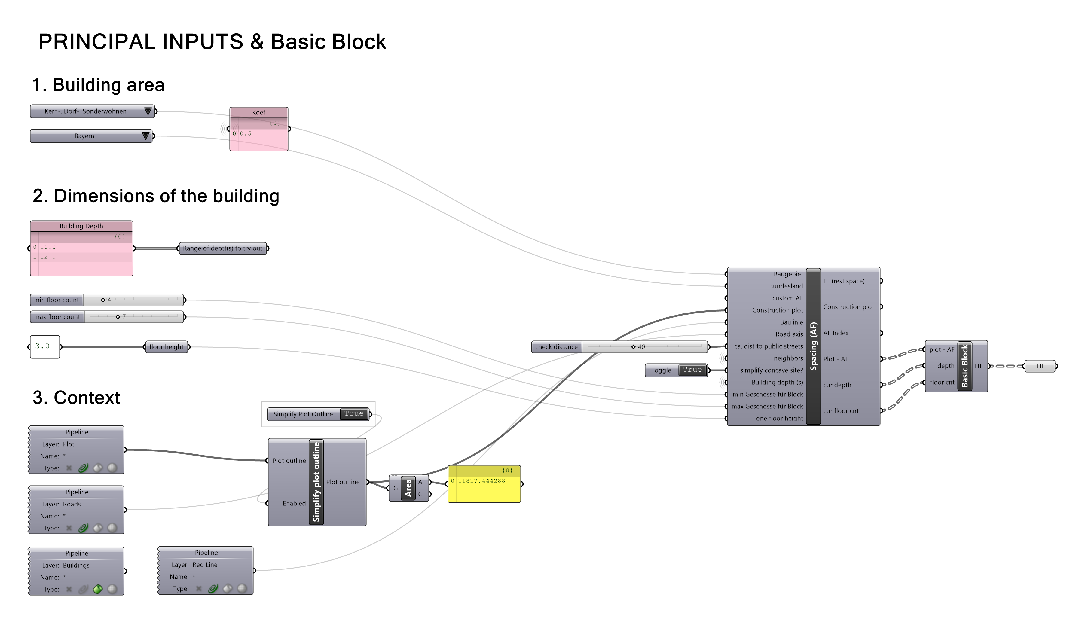
In order to start the generation, the minimal requirement is a closed planar polyline in Rhino, representing the construction site. Additionally, you can add a layer with lines, representing the street axis, as well as the neighbor buildings context on a separate layer. Both those layers will then be considered during the generation.
It is as well required to select the location of the building area in order to derive the correct spacing (see the video above to learn about the spacing concept). Further, you can select multiple values for the building depth to try out, as well as set up a range of the floors count for the basic block. The output of this step is a closed block (or a range of those) around the construction plot perimeter, considering the required spacing based on the block height.
It is possible though, that the spacing should be neglected, in case that your construction plot is placed within existing blocks and thus you should continue the street profile, placing the buildings right along the plot edge. In this case, you can just draw the lines in Rhino to indicate where the spacing should not appear, and insert them into „Baulinie“ input.
The resulting generations are gathered at the „House Instance“ data type, which is a combination of six different parameters: plot after spacing; surfaces; outlines (façade lines towards the street); inlines (façade lines towards towards the inner yard); depth of a building (as a number), floor count (as a number). Using Surface and Floor Count you can display the geometry preview as well as calculate the basic performance indicators, such as FAR, Site Occupancy, or Total Built Area.
1b. Actions over the Block.

1b.1| DELETE EDGES
This action can delete one or multiple edges to reduce the density or to solve a too narrow concave block intersection. You can select the edge to start with and decide on the number of edges to delete.

1b.3| SETBACKS CORNERS
This action creates a setback at the corner if the length of the adjusting edges is sufficient and the setback does not cause an intersection. You can select the edge for generation, dimensions range for the setback parameters and a seed for the randomness.

1b.5| CORNERBREAKS
This action creates passageways in the block‘s corners, thus avoiding the creation of corners that are rather difficult for the later apartments placement. You can change the width of the passageways as well as the directions of the cuts.

1b.7| ENVELOPES
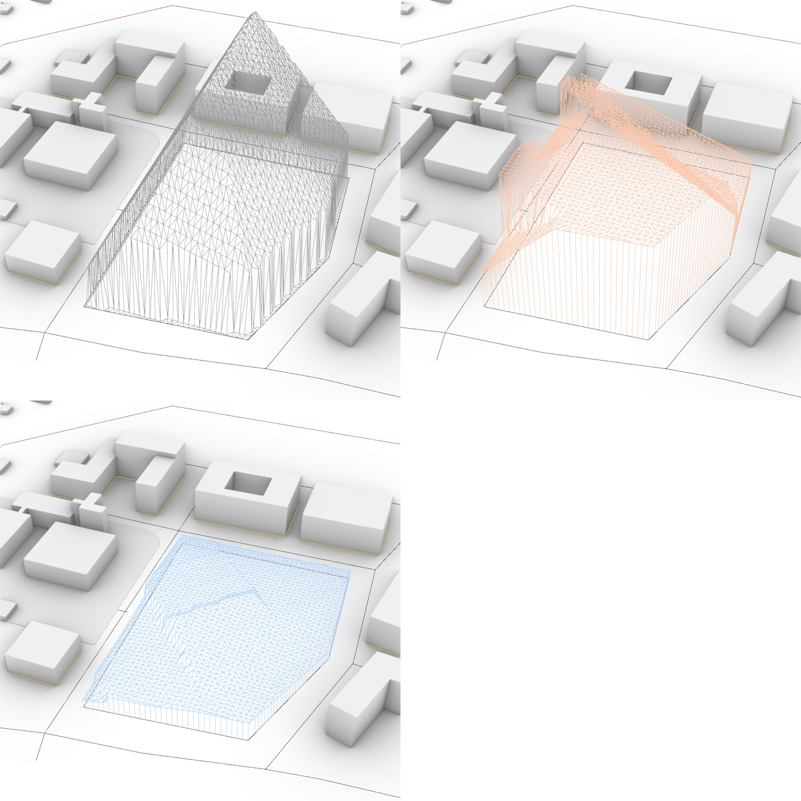
This action creates a spacing envelope, as well as both summer and winter solar envelopes (with the help of LadyBug tools). Informed by those envelopes, you can place buildings that act according to the local requirements, or that are placed to minimize the influence on the lighting conditions for the neighbor buildings around the given site.

1b.| YARD BUILDINGS
This action creates buildings within the block yard after the user-drawn axis. You can select the depth of the yard buildings as well as their floor count.

1b.2| SETBACKS EDGES
This action creates a setback along an edge if the edge length is sufficient. You can selecte the edge for generation, dimensions range for the setback parameters and a seed for the randomness.

1b.4 | RANDOM BREAKS
This action creates passageways through the block perimeter at either random, or user-driven spots. You can select the total amount of area to delete or the total width of the passageways, as well as the number of random options to try out per input block.

1b.6 | REDUCE HEIGHT
This action cuts the block through the corners and reduces the floor count of some of the building fragments. Here, you can indicate the total amount of area to delete. This actions creates several different height profiles per input block.

1b.8 | TOWERS
This action places one or two towers along the existing block perimeter in order to gain extra area. You can select the desired area per tower, restrict the extra floors, or assign a point where the tower should be located if you dont want random generations to appear. The limit of tower height is resulting from the envelopes script.

1b.10 | ROOFTOPS
This action creates offsetted rooftop floors over the block perimeter. You can decide on the orientation of the buildings (toward street/yard), depth, and their overall amount.
1c. Examplatory Generation Sequence
In the following video you‘ll find an examplatory combination of actions for generating a bunch of various building volumes for one construction site, including the parameters setting for each of the actions. Keep in mind that the suggested sequence is not the only possible one, and you can try to arrange actions in another way, and thus receive different results.
*please remember to unblock the .gha components before inserting them into your Libraries folder
Part 2:
Slabs Generation Components
2a. Single Plot Generation.
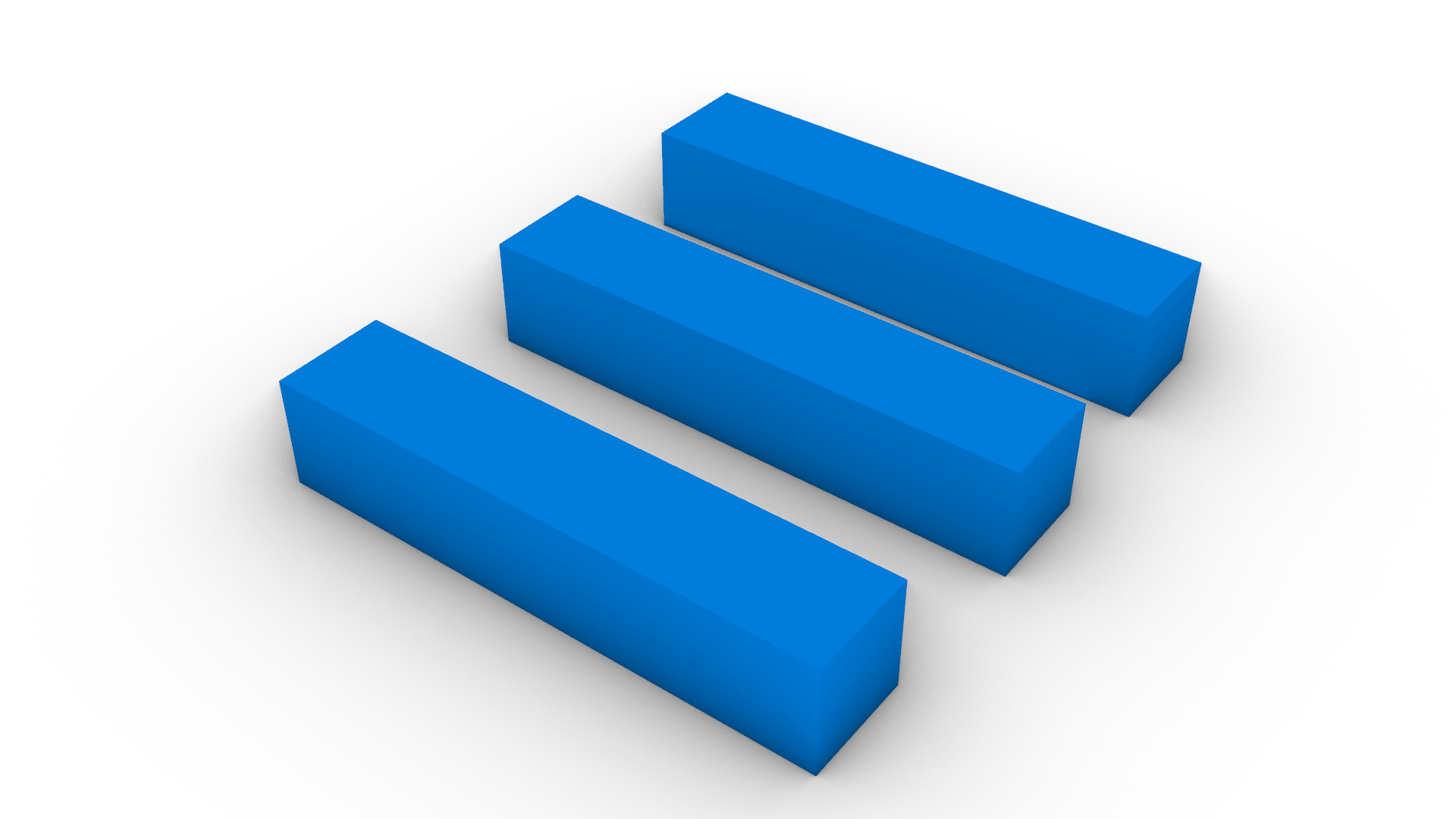
Here, the generation logic is slightly different than it was the case for the block typology. Whereas block was about offsetting and further modifying the site outline, slabs is about the pattern of the placement of several simple forms on the given site. Therefore, it is possible to order several slabs at one site. First, the site edges are translated into 4 characteristic edges based on the angles between them.
Further, slabs can appear along each of the edges – as long as the space is sufficient.
Depending on the selected order of the edges, the pattern of the slabs allocation can differ greatly.
Accordingly, each further parameter to influence the slabs pattern is repeated four times in order to allow different variations along each of the edges. In all further parameters, the order of the values will be applied accordingly to your selected order of the site edges. You can re-adjust the edges order at any later moment of the generation. Below, you can find a short video with the overview of the parameters that you can influence for the slabs typology.
2b. Subdivision of Complex Concave Sites and Multiple Plots Generation
In case of large area plots, such generation might cause monotonous strict patterns, non usable for modern urban plannings. In order to escape this, we developed a method on the subdivision of the big concave plots into smaller and simpler sub-fragments. Those sub-plots can then be filled with slabs in a single direction.
In the previous part, there were nine parameters for each slab raw at a single edge. In the case of generating slabs for multiple plots at the same time, the number of parameters gets multiplied accordingly. As follows, taking control over generation becomes exhausting. That is why for the multiple plots generation it was decided to leave only single-direction slabs. However, the user can decide between different orientation patterns as well as subdivision patterns himself, thus still exploring the design space to a several extent. In the following video you can see the brief overview of parameters to guide the generation for the slabs typology at multiple sites.


